[MPE] Solar Emulation and Inverter Testing
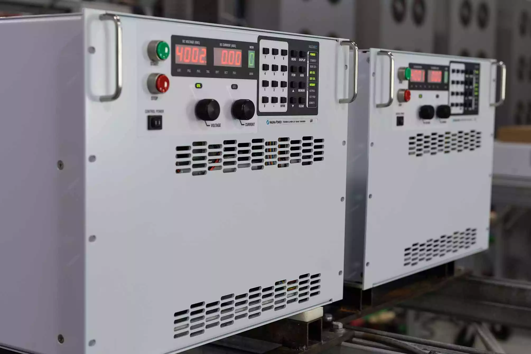
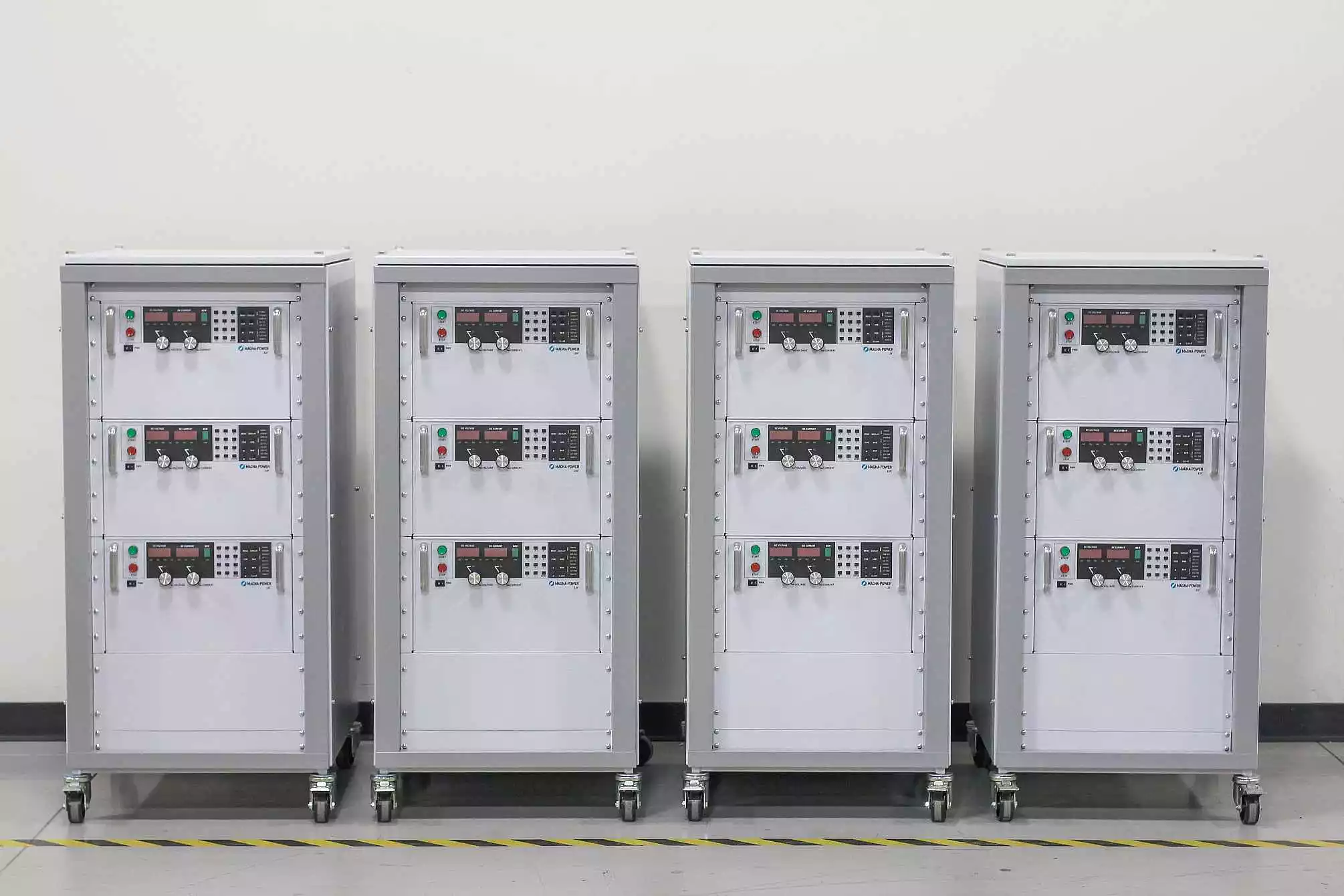
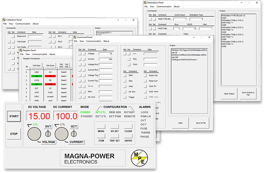
Solar Emulation and Inverter TestingOverviewSolar arrays produce a DC output with non-linear characteristics varying as a function of temperature and irradiance. Devices directly connected to solar arrays, such as solar inverters, account for these variations to both characterize the array’s output and maximize the amount power converted. Solar array output characteristics vary significantly from a standard DC power supply, requiring additional controls to be implemented for a DC power supply to satisfy these testing requirements.Solar Array CharacteristicsThe voltage and current characteristics of solar arrays fluctuate with temperature and irradiance of the panels; loosely defined by irradiance affecting output current and temperature affecting output voltage. Solar array connected devices, such as solar inverters, must maximize the solar array’s power output by locating the maximum operating point. In addition, devices equipped with maximum power point tracking must also adjust the operating point to account for fluctuations in temperature and sunlight.Why Magna-Power ElectronicsSolar Array Emulation or Standard Power Supply: Magna-Power Electronics Photovoltaic Power Profile Emulation software enables any Magna-Power Electronics power supply to emulate the non-linear characteristics of a solar array and vary these characteristics as a function of time. Any Magna-Power Electronics power supply can be toggled back and forth between standard power supply operation, with CV and CC modes, or solar emulation operation. This dual operation enables maximum utilization of the test equipment for a wide variety of applications.Accurate Programming and Measurement: Magna-Power Electronics programming and measurement accuracy is among the highest in the industry. Engineers can rely on measurements directly from the power supply for calibration, meaning less instrumentation and complication in test environments.Harmonic Neutralization: Magna-Power Electronics has pioneered harmonic neutralization technology, enabling central inverter testing into multi-megawatts with as high as 48-pulse waveforms produced by the power supply.High Slew Rate Option (+HS): The high slew rate option, available for all Magna-Power Electronics products, provides reduced output capacitance and use of film capacitor technology instead of standard aluminum electrolytic. For solar inverter testing, the high slew rate option is highly recommended, as the reduced output capacitance means less interaction with inverter ripple components, while affording the power supply with a higher bandwidth.Solar Array Emulation SoftwareMagna-Power Electronics Photovoltaic Power Profile Emulation (PPPE) Software generates non-linear voltage/current (V/I) profiles based on the EN50530 standard, allowing variation of these V/I characteristics as a function of temperature and sunlight. These profiles can be sequentially sent to the power supply, allowing variations in solar parameters to change the power supply output characteristics over user-defined intervals. In addition, an interpolation function allows automated profile generation between curves, for smooth transitions from one temperature and irradiance condition to another. This functionality can be used, for example, to transition from cloudy winter conditions to summer sunny conditions. Alternatively, a profile may be stored internally to the power supply, for use when disconnected from a computer. In addition, a command export is available to leverage PPPE’s ease of solar profile generation from an automated environment such as LabVIEW or Visual Studio.Figure 1. Main Screen of Magna-Power Electronics Photovoltaic Power Profile Emulation SoftwareFigure 2. Photovoltaic Power Profile Emulation software's Live Output Viewer screenThree different methods are provided for generating profiles:- Reference Parameters: If a reference solar cell and array characteristics are known, profiles can be generated using solar cell parameter values: Tref, Irref, Vmp, Imp, Voc, Isc, β, and α. A drop-down is provided to select polysilicon (cSi) or thin film technology, to autopopulate the β and α values in accordance with the EN50530 standard. After populating the reference values, generating a new curve is as simple as specifying a temperature and irradiance value for each new curve.- 4-Parameter: The simplest profile generation method, profiles can be generated using just the maximum power point, max voltage (open-circuit), and max current (short-circuit): Vmp, Isc, Voc, and Isc. - Up to 50-manual points: A manual curve can be used with PPPE software, either by manually entering voltage and current points, or importing values from a comma separated value (.csv) file. A maximum of 50-point can be entered, however, the power supply will perform a piecewise linear approximation between these points during operation, ensuring high resolution.A live output viewer provides a full window simultaneously displaying voltage, current, and power output and tracks these parameters over time. This window provides a clear overview of the connected load’s ability to track changes in temperature and irradiance over time. Data logging functionality is provided to save output voltage, current, and power values as well as the defined output characteristics over time.Expansive and Modular Product OfferingMagna-Power Electronics offers the broadest range of standard programmable DC power supplies with solar emulation capability. Magna-Power Electronics rack-mount products are offered as low as 2 kW and floor-standing systems as large as 4,000 kW, with voltages as high as 4,000 Vdc (floating) and currents as high as 24,000 Adc. The entire product line features identical controls and identical programming options. Units come standard with front panel step-less rotary control, RS-232 computer interface, and isolated 37-pin analog/digital external control. Options such as LXI TCP/IP Ethernet (+LXI), IEEE 488.2 GPIB (+GPIB), and USB Edgeport (External) (+USB) are available as additional programming interfaces. All programming interfaces support the basic SCPI command set and are compatible with the Photovoltaic Power Profile Emulation software. In addition, Remote Interface Software for computer-based front panel control and IVI drivers are included, for ease of programming remote. As power requirements grow, so too can the power solar array emulator. With the modular building blocks offered by Magna-Power Electronics power supplies, units can be added in master/slave parallel or series at any time. For maximum flexibility, units may be used individually, in smaller master/slave systems, or all together in one large system assuming all the module are like models.For central inverter testing, MT Series products are offered in 100 kW, 150 kW, and 250 kW module sizes. The independent IGBT-based MT Series units are among the largest standard switch-mode power supplies on the market, minimizing the number of switching components when comparing to smaller module sizes. Scaling in the multi-megawatts is accomplished using the UID47 device, which provides master/slave control: one power supply takes command over the remaining units, for true system operation.All Magna-Power Electronics power supplies can be configured for master/slave parallel or series operation with other equivalently rated power supplies. Plug & Play master/slave operation is provided by the UID47 device, which interconnects control signals between the power supplies.For burn-in applications, central inverters demand high voltages and high currents, but often not simultaneously. Therefore, having a power supplies capable of being reconfigured in different arrays of series and parallel modules is advantageous and, furthermore, offers the most cost-effective solution. For example, consider distinct inverter burn-in requirements for 2000 Vdc at 500 Adc and also 500 Vdc at 2000 Adc. Rather than specifying a power supply capable of both 2000 Vdc and 2000 Adc, a much smaller and less expensive solution can be specified using Magna-Power Electronics modular configuration, changing the power supplies from series to parallel operation for the distinct test requirements.Reconfiguring the power supply’s output stage from series to parallel is accomplished through an external contactor or low-cost throw switch. Reconfiguration should not take place while the outputs are energized, instead, the power supply should be at zero volts and amperes. In addition, UID47 control wires must also be changed, as the slave unit(s) receive different signals depending on series or parallel operation. Magna-Power Electronics application engineers are available to aid with best practices for this process.High Slew Rate Option (+HS)The high slew rate option solves several limitations inherent in switching power supply design. Rapid voltage transitions require internal electronics to supply the energy to charge and discharge output capacitors. Peak currents internal to the power supply define slew rate; utilizing less capacitance enables voltage transitions in shorter time periods. Additionally, less capacitance reduces requirements for discharge demands during open circuit conditions.The standard output stage Magna-Power Electronics power supplies has been designed to provide the lowest possible output ripple voltage within the constraints of available components, size, and cost. Part of the output stage consists of a bank of aluminum electrolytic capacitors which has the desired electrical properties to provide this function. These components require bleed resistors to discharge any voltage when the power supply has no load and is disabled. While the presence of these components and the resulting performance are normally industry accepted, there are applications where lower output capacitance and lower loss bleed resistors are extremely desirable and higher ripple voltage is acceptable. To meet this need, a high-slew rate option is available which has an output stage consisting of low capacitance film and aluminum electrolytic capacitors.For photovoltaic emulation applications, higher bandwidth and lower output capacitance enable improved performance with higher speed, maximum power tracker algorithms. Maximum power tracker circuitry deviates the operating point of photovoltaic arrays to determine maximum power output. Slow responding emulation sources can present a problem when the speed of the algorithm exceeds that of the source. Furthermore, with lower output capacitance, changes in the operating point and transients, caused by shorting the solar inverter input, produce lower unwanted input currents.High Isolation Output Option (+ISO)When tying units together in series, it’s important to note the product’s output isolation rating, which varies depending on the product series and model, as per the product’s specifications. The product’s isolation should not be exceeded by a system of series configured power supplies. The following table provides a quick reference for available output isolation ratings:Table 1. Output isolation rating for models with the High Isolation Output (+ISO) option Standard Output Isolation for Models Rated 1000 Vdc and Below, No OptionOutput Isolation for Model Rated 250-1000 Vdc With +ISO OptionStandard Output Isolation for Models Rated Above 1000 Vdc, No OptionXR Series1000 VdcN/AN/ATS Series1000 Vdc±(2000 Vdc + Vo/2) ±(2000 Vdc + Vo/2) MS Series1000 Vdc±(2000 Vdc + Vo/2) ±(2000 Vdc + Vo/2) MT Series1000 Vdc4000 Vdc4000 VdcNote: Vo is the product's output voltage ratingThe standard isolation for XR Series, TS Series, and MS Series models A high isolation option (+ISO) is available for TS Series and MS Series products 1000 Vdc and below, enabling output isolation up to 2000 Vdc + Vo/2 fully floating, where Vo is the product’s output voltage rating. MT Series products 400 Vdc and above are available with 4000 Vdc output isolation.Central Inverter Energy RecyclingDevelopment and production megawatt-scale central inverters place unique requirements on testing equipment and power installations. The AC output of the inverter can be fed back into the input of DC supply, allowing power recycling. The solar inverter output is commonly recycled into the input of the DC power supply, allowing the power system to be rated to supply only the overall losses; a small fraction of the total power conversion. With this type of configuration, power harmonics play a critical role on testing performance and reliability.Input current harmonics are a by-product of nearly all power supplies. Power can only be delivered to the load if the frequency and phase of the voltage and current match. For a three phase power supply using a three phase input rectifier, the input current has a theoretical spectrum of 6n±1 where n is an integer incrementing from 1; this is known as a 6-pulse waveform. This means that a power supply with a three phase input rectifier will produce input currents at 1, 5, 7, 11, 13, 17, 19 ... times the fundamental frequency. The theoretical magnitude decays as the reciprocal of the harmonic component. The 5th and 7th harmonic components have magnitudes of 20% and 14% of the fundamental component, respectively.Harmonics currents in power systems can find unusual paths and can cause problems if the magnitude is significant and there are loads sensitive to harmonic frequencies. For example, lighting ballasts have series connected capacitors and inductors which can be excited by harmonic currents. IEEE has introduced standard, IEEE 519, which defines recommended limits. Implementing this standard requires knowledge of the power system and other loads producing harmonics. Unfortunately, the standard can allow the same power supply to possibly exceed limits in one application and not in another. In the same respect, a power supply may or may not cause a harmonic related problem with or without meeting IEEE 519. The best solution to minimize the risk of a harmonic problem is to eliminate the harmonic current at the source.Magna-Power Electronics harmonic neutralizers suppress families of harmonics by increasing the number of power phases. It can be used when multiple power supplies are used in series or parallel and are equally loaded. Harmonic neutralizers can produce 12-pulse, 18-pulse, 24-pulse or 48-pulse waveforms which have harmonic current components on the order of 12n±1, 18n±1, 24n±1, or 48n±1, respectively. Figure 1 shows the theoretical difference between 6-pulse and 12-pulse waveforms; 18-pulse waveforms are similar, but with more steps. Figure 2 shows the resulting spectral differences. HN Series harmonic neutralizers are protected with appropriate sized circuit breaker.All 250 kW MT Series products come with an integrated 12-pulse harmonic neutralizer, meaning 250 kW sources will produce 12-pulse AC waveforms as standard. To reach higher power levels, multiple 250 kW MT Series units are tied together in master/slave parallel and/or series using the UID47 device. For central inverters in the multi-megawatts, Magna-Power Electronics offers a 500 kW 24-pulse harmonic neutralizer, HN500, or 48-pulse harmonic neutralizer, HN1000, to meet even the most demanding harmonic requirements. When this option is supplied with a large MT Series system, one HN500 device is used with every two 250 kW power supplies or one HN1000 is used with every four 250 kW power supplies. The incoming AC power is supplied to the HN500/HN1000’s primary for a single point of entry. Cabling from the HN500/HN1000’s secondary side to the power supply’s AC input is provided by Magna-Power Electronics.SummaryMagna-Power Electronics offers a broad range of solutions for solar inverter testing requirements. The Photovoltaic Power Profile Emulation software provides non-linear V/I curve generation in accordance with the EN50530 standard, data logging, as well as sequential emulation of curves through a Magna-Power Electronics power supply. Options such as the High Slew Rate Output (+HS) and High Isolation Output (+ISO) deliver output upgrades for specific solar inverter testing requirements. Finally, Magna-Power Electronics novel harmonic neutralizing technology enables clean AC waveforms, even while utilizing switched-mode power supply technology into the multi-megawatts.
자세히 보기