Test & Measurements

제품특징
  • 50 MHz 대역폭
  • 1 GSa/s 샘플링 속도
  • 200k 포인트
  • 20 MHz 파형 생성기 내장(기본 제공)
  • Bode 플롯(FRA), 수학, FFT, 직렬 프로토콜 분석을 포함한 전문적인 측정 제공(기본 제공)
  • 내장된 도움말 및 교육 신호로 사용법이 편리
  • 초당 100,000개 파형의 업데이트 속도로 더 자세한 신호 정보 확인 가능
  • 포함 내역:
  • 표준 3년 보증(액세서리인 경우 90일)
  • 인증서 제공 시 5년 교정
  • 표준 보안 삭제
  • 두 개의 N2142A 75 MHz 10:1/1:1 전환 가능 패시브 프로브
  • 다양한 언어 도움말 제공
  • Keysight 원격 조정 Software BenchVue Basic 무료 제공


6개 제품의 기능이 하나의 장비로!

1000 X 시리즈는 업계 최고 수준의 소프트웨어 분석 기능과 6-in-1 통합을 통해 전문가 수준의 오실로스코프 기능을 제공합니다. 이 제품은 비용 절감과 작업대 공간 절약을 도와주며 다음과 같은 기능을 제공합니다:


오실로스코프

1000 X 시리즈는 저렴한 가격에도 품질을 타협하지 않는 오실로스코프 제품군입니다.

각 모델은 고가의 오실로스코프와 경쟁할 수 있는 측정 및 표준 소프트웨어 분석 기능을 제공합니다.

.

.

.

.


.

.


WaveGen (내장 20 MHz 함수 발생기와 변조 기능)

(EDUX1052G, DSOX1202G, DSOX1204G 모델에만 해당)

1000 X 시리즈는 변조 기능이 있는 20 MHz 내장 함수 발생기를 제공합니다. 이는 공간과 예산이 중요한 교육 또는 설계 실험실에 이상적입니다.

내장 함수 발생기는 테스트할 장치에 대해 사인파, 정사각파, 램프파, 펄스, DC, 그리고 잡음 파형의 자극 출력을 제공합니다. AM, FM, FSK 등의 맞춤형 변조 설정을 추가하여 신호를 조정할 수 있습니다.

별도의 함수 발생기를 구입할 필요 없이 새로운 오실로스코프에 통합된 함수를 사용할 수 있습니다..

.

.

.


하드웨어 기반의 직렬 프로토콜 디코딩 및 트리거링

1000 X 시리즈는 하드웨어 기반의 직렬 통신 분석을 지원하는 강력한 프로토콜 분석기입니다.

타사 오실로스코프는 소프트웨어 후처리 기술을 사용해 파형 및 디코딩 업데이트 속도를 늦추는 반면, 1000 X 시리즈는 하드웨어 기술을 통해 더 빠른 디코딩을 제공합니다.

이를 통해 드물게 발생하는 직렬 통신 오류를 포착할 가능성을 높입니다.

EDUX 모델은 I2C 및 UART/RS232를 지원하며, DSOX 모델은 I2C, SPI, UART/RS232, CAN 및 LIN을 지원합니다.

.

.

.

.


주파수 응답 분석기 (EDUX1052G, DSOX1202G,DSOX1204G 모델에만 해당)

주파수 응답 분석(이득 및 위상 보드 플롯)은 증폭기, 수동 네트워크, 전원 공급 피드백 네트워크를 특성화하는 데 중요한 측정입니다. 보드 플롯은 또한 모든 전기공학 학생들이 배워야 할 기본 개념 중 하나입니다.

1000 X 시리즈의 주파수 응답 분석 기능(G 모델에서 표준으로 제공)은 학생들이 수동 RLC 회로와 증폭기의 이득 및 위상 성능을 이해하는 데 도움을 주는 완벽한 도구입니다.

이 기능은 주파수에 따른 이득 및 위상 측정을 통해(보드 플롯) 이루어집니다. 일반적으로 벡터 네트워크 분석기(VNA)와 저비용 주파수 응답 분석기가 이러한 측정에 사용되지만, 이제는 1000 X 시리즈의 내장 WaveGen과 보드 플롯 기능을 활용해 쉽고 저렴한 이득 및 위상 분석이 가능합니다.

또한, DSOXBODE 보드 플롯 교육 키트와 주파수 응답 측정(보드 플롯)을 배우는 공학 학생들을 위한 다운로드 가능한 튜토리얼과 실험 가이드도 제공됩니다.


.

.

.


디지털 볼트미터

1000 X 시리즈는 각 오실로스코프 내에 3자리 디지털 볼트미터(DVM)를 통합하고 있습니다.

볼트미터는 오실로스코프 채널에 연결된 프로브를 통해 작동하지만, 그 측정은 오실로스코프의 트리거링 시스템과 분리되어 있어 동일한 연결로 DVM과 트리거된 오실로스코프 측정을 모두 수행할 수 있습니다.

오실로스코프 캡처를 설정하지 않고도 AC RMS, DC, DC RMS를 빠르게 측정할 수 있습니다. 볼트미터 결과는 항상 표시되어, 이러한 빠른 특성화 측정을 쉽게 확인할 수 있습니다.

내장 DVM은 1000 X 시리즈 오실로스코프에 기본으로 제공됩니다.

.

.

.

.


주파수 카운터

각 오실로스코프에는 5자리 주파수 카운터가 통합되어 있습니다. 주파수 카운터는 오실로스코프 채널에 연결된 프로브를 통해 작동하여 카운터와 트리거된 오실로스코프 측정을 동일한 연결로 수행할 수 있습니다.

오실로스코프 캡처를 설정하지 않고도 주파수를 빠르게 측정할 수 있습니다. 고해상도 주파수 측정 결과는 항상 표시되어 빠른 특성화 측정을 쉽게 확인할 수 있습니다.


.

.

.

.

.


Performance Characteristics


Oscilloscope overview


EDUX1052A/EDUX1052G

DSOX1202A/DSOX1202G

DSOX1204A/DSOX1204G

Bandwidth (–3 dB) 1, 2

50 MHz

70 MHz

70 MHz


100 MHz (option D1202BW1A)

100 MHz (option D1200BW1A)


200 MHz (option D1202BW2A)

200 MHz (option D1200BW2A)

Calculated rise time (10 to 90%)

≤ 7 ns

≤ 5 ns (70 MHz base model)

≤ 5 ns (70 MHz base model)


≤ 3.5 ns (with 100 MHz option)

≤ 3.5 ns (with 100 MHz option)


≤ 1.7 ns (with 200 MHz option)

≤ 1.7 ns (with 200 MHz option)

Input channels

2

2

4

Maximum sample rate

1 GSa/s (all channels)

2 GSa/s (all channels)

1 GSa/s (if ext. trigger is displayed)

2 GSa/s (one- or half-channeloperation)
1 GSa/s (three- or four-channel operation)

Maximum memory depth

200 k points (all channels)

2 M points (all channels)

1 M points (if ext. trigger is displayed)

2 M points (one- or half-channeloperation)

1 M points (three- or four-channel operation)

Waveform update rate

≥ 100,000 waveforms/sec

≥ 200,000 waveforms/sec

≥ 200,000 waveforms/sec


Vertical system


All Models

Input coupling

DC, AC (10 Hz cutoff frequency)

Input impedance/capacitance

1 MΩ ± 2%, 16 pF ±3 pF

Input sensitivity range4

500 μV/div to 10 V/div

Standard probes

N2142A 1/10 switchable 75 MHz (2 included in EDUX1052A/EDUX1052G)
N2140A 1/10 switchable 200 MHz (2 included in DSOX1202A/DSOX1202G)
N2140A 1/10 switchable 200 MHz (4 included in DSOX1204A/DSOX1204G)

Probe attenuation factor

0.1X to 10,000X in 1-2-5 sequence; (–20 dB to +80 dB in 0.1 dB steps)

Hardware bandwidth limits

Approximately 20 MHz (selectable)

Vertical resolution

8 bits

Invert signal

Selectable

Maximum input voltage

150 Vrms, 200 Vpk

DC vertical accuracy

± [DC vertical gain accuracy + DC vertical offset accuracy + 0.25% full scale]

DC vertical gain accuracy 1

+3% full scale (≥ 10 mV/div)


+4% full scale (< 10 mV/div)

DC vertical offset accuracy

± 0.1 div ± 2 mV ± 1% of offset setting

Skew

Channel to channel: 1 ns (without deskew)


Channel to external: 2 ns (without deskew)

Offset range

500 uV/div to 200 mV/div: +2 V

> 200 mV/div to 10 V/div: +100 V


  1. Denotes warranted specifications; All others are typicalSpecifications are valid after a 30-minute warm-up period and from ± 10 °C user calibration temperature.

  2. Bandwidth specifications apply for 1 mV/div to 10 V/div vertical settings. Bandwidth at the 500 μV/div vertical setting is limited to 20 MHz.

  3. Half-channel operation on a 2-channel model refers to two-channel operation when using channel-1 or channel-2 AND channel-3 or channel-4.

  4. 500 μV/div is a 2X digital magnification of 1 mV/div setting.


    Find us at www.keysight.com Page 12

    Performance Characteristics (continued)

    Horizontal system


    All Models

    Time base range

    5 ns/div to 50 s/div (50 MHz, 70 MHz , and 100 MHz models), 2 ns/div to 50 s/div (200 MHz models)

    Horizontal resolution

    2.5 ps

    Timebase accuracy 5

    50 ppm ± 5 ppm per year (aging)

    Timebase delay time range

    Pre-trigger: Greater of 1 screen width or 200 μs


    Post-trigger: 1 to 500 s

    Channel to channel deskew range

    ± 100 ns

    Δ Time accuracy (using cursors)

    ± (time base acc. x reading) ± (0.0016 x screen width) ± 200 ps (same channel)

    Modes

    Main, zoom, roll, XY

    XY

    X = channel 1, Y = channel 2, Z = external trigger, 1.4 V blanking


    Acquisition system

    Bandwidth: Maximum bandwidth. Phase error at 1 MHz: < 0.5 degree


    EDUX1052A/EDUX1052G

    DSOX1202A/DSOX1202G
    DSOX1204A/DSOX1204G

    Maximum sample rate


    1 GSa/s

    2 GSa/s (2 ch operation), 1 GSa/s (4 ch operation)

    Maximum record length


    200 k points

    2 M points (2 ch operation), 1 M points (4 ch operation)

    Acquisition mode

    Normal

    Default mode

    Default mode


    Peak Detect

    Capture glitches as narrow as 10 ns at all time base
    settings

    Capture glitches as narrow as:

    70 MHz model: 10 ns at all time base settings

    100 MHz model: 5 ns at all time base settings
    200 MHz model: 2.5 ns at all time base setting


    Averaging

    Selectable from 2, 4, 8, 16, 64, ... to 65,536

    Selectable from 2, 4, 8, 16, 64, ... to 65,536


    High Resoluti

    on Real-time boxcar averaging reduces random noise
    and effectively increases vertical resolution to 12 bits
    of resolution when ≥ 20 μs/div at 1 GSa/s

    Real-time boxcar averaging reduces random noise
    and effectively increases vertical resolution to 12 bits
    of resolution when ≥ 20 μs/div at 2 GSa/s


    Segmented

    Not available

    Segmented memory optimizes available memory for
    data streams that have long dead times between
    activity.

    Maximum number of segments = 500
    Minimum trigger re-arm time = 1 µs (1,000,000

    waveforms/sec in Segmented acquisition mode)

    Time mode

    Normal

    Default mode

    Default mode


    Roll

    Displays the waveform moving across the screen
    from right to left. Available at the timebase settings
    of 50 ms/div or slower

    Displays the waveform moving across the screen from
    right to left. Available at the timebase settings of 50
    ms/div or slower


    XY

    Displays the volts-versus-volts display

    Displays the volts-versus-volts display


    X = Channel 1, Y = Channel 2

    X = Channel 1, Y = Channel 2


    Z = External trigger, 1.4 V blanking

    Z = External trigger, 1.4 V blanking


    Phase error at 1 MHz: < 0.5 degree

    Phase error at 1 MHz: < 0.5 degree

    Autoscale


    Finds and displays all signals connected to analog
    input channels and the external trigger input. Sets
    trigger type to rising edge at ~50% on external
    (highest priority source), or lowest numbered
    channel with a signal that exceeds ~10 mVpp.

    Optimizes vertical scaling for stacked waveforms
    and sets timebase to display ~ 1.8 periods. Can be
    customized to function on just channels that are

    previously turned on and displayed.

    Finds and displays all signals connected to analog
    input channels and the external trigger input. Sets
    trigger type to rising edge at ~50% on external
    (highest priority source), or lowest numbered
    channel with a signal that exceeds ~10 mVpp.

    Optimizes vertical scaling for stacked waveforms and
    sets timebase to display ~ 1.8 periods. Can be
    customized to function on just channels that are

    previously turned on and displayed.

  5. Denotes warranted specifications; All others are typicalSpecifications are valid after a 30-minute warm-up period and from ± 10 °C user calibration temperature.


    Find us at www.keysight.com Page 13

    Performance Characteristics (continued)


    Trigger system


    All Models

    Trigger sources

    Analog channels, line6, external, WaveGen, WaveGen modulation FM/FSK

    Trigger modes

    Normal (triggered): Requires trigger event for oscilloscope to trigger


    Auto: Triggers on selected source or automatically triggers (asynchronously) in absence of a valid trigger event


    Single: Triggers only once upon detection of a valid trigger event


    Force: Front panel button that forces an asynchronous trigger while in the Normal trigger mode

    Trigger coupling

    DC: DC coupled trigger


    AC: AC coupled trigger, cutoff frequency: ~ 10 Hz


    HF reject: High frequency reject, cutoff frequency ~ 50 kHz


    LF reject: Low frequency reject, cutoff frequency ~ 50 kHz


    Noise reject: Selectable OFF or ON, decreases trigger sensitivity 2X

    Trigger holdoff range

    60 ns to 10 s


    Trigger sensitivity


    EDUX1052A/EDUX1052G

    DSOX1202A/DSOX1202G
    DSOX1204A/DSOX1204G

    Internal 7

    Greater of:

    0.6 div or 2.5 mV (≤ 10
    MHz)

    0.9 div or 3.8 mV (10 to 50

    MHz)

    Greater of:

    0.6 div or 2.5 mV (≤ 10 MHz)

    0.9 div or 3.8 mV (10 to 70 MHz)

    1.2 div or 5 mV (70 to 200 MHz)

    External

    ≤ 10 MHz: 250 mVpp

    ≤ 10 MHz:

    20 mVpp (1.6 V range)

    100 mVpp (8 V range)

    10 to 50 MHz: 500 mVpp 10 to 200 MHz:

    100 mVpp (1.6 V range)

    500 mVpp (8 V range)


    Trigger level range


    EDUX1052A/EDUX1052G

    DSOX1202A/DSOX1202G
    DSOX1204A/DSOX1204G

    Internal

    ± 6 div from center-screen

    ± 6 div from center-screen

    External 8

    ± 8 V

    ± 1.6 V or ± 8 V selectable

  6. Line trigger to ≤ 60 Hz.

  7. Denotes warranted specifications; All others are typicalSpecifications are valid after a 30-minute warm-up period and from ± 10 °C firmware calibration temperature.

  8. Input voltage must remain within these limits for proper operation.


    Find us at www.keysight.com Page 14

    Performance Characteristics (continued)


    Trigger type selections


    EDUX1052A/EDUX1052G

    DSOX1202A/DSOX1202G
    DSOX1204A/DSOX1204G

    Edge

    Trigger on a rising, falling, alternating or either edge of any source

    Pattern/state

    Not available

    Trigger when a specified pattern/state on any
    combination inputs is entered 9

    Pulse width

    Trigger on a pulse of a selected channel with a time duration that is ‘less than a value,’
    ‘greater than a value’ or ‘inside a time range’

    Range minimum: 10 ns, 10 s max

    Setup and hold

    Not available

    Trigger and clock/data setup and/or hold time
    violation. Setup time can be set from –7 ns to 10 s.
    Hold time can be set from 0 s to 10 ns

    Rise/fall time

    Not available

    Trigger on rise-time or fall-time edge-speed violations
    (< or >) based on a user-selectable threshold and

    time setting range between 5 ns and 10 s

    Video

    Trigger on all lines or individual lines; odd/even or all fields from the composite video; or
    broadcast standards (NTSC, PAL, SECAM, and PAM-M)

    I2C

    Trigger at a start/stop condition or user-defined frame with address and/or data values. Also,
    trigger on missing acknowledge, restart, EEPROM read and 10-bit write

    RS-232/422/485/UART

    Trigger on Rx or Tx start bit, stop bit, data content or parity error

    SPI

    Not available

    Trigger on SPI (Serial Peripheral Interface) data
    pattern during a specific framing period.

    Supports positive and negative chip select
    framing as well as clock idle framing. Supports
    MOSI or MISO (4-channel models) data as half

    duplex data

    CAN

    Not available

    Trigger on CAN (controller area network) version
    2.0A and 2.0B signals. Trigger on the start of
    frame (SOF) bit, remote transfer request frame
    ID (RTR), data frame ID (~RTR), remote or data
    frame ID, data frame ID + data, error frame, all
    errors, acknowledge error, or overload frame.

    LIN

    Not available

    Trigger on LIN (Local Interconnect Network) sync
    break, frame ID, frame ID + data, parity error, or
    checksum error


  9. The pattern must have stabilized for a minimum of 5 ns to qualify as a valid trigger condition.


    Find us at www.keysight.com Page 15

    Performance Characteristics (continued)


    Serial protocol analysis/decode (standard)


    EDUX1052A/EDUX1052G

    DSOX1202A/DSOX1202G
    DSOX1204A/DSOX1204G

    I2C

    Baud Rate: Up to 3.4 Mbps
    Address size: 7-bit or 8-bit

    Number of time-correlated decode traces:
    One plus protocol lister/table

    Baud rate: Up to 3.4 Mbps
    Address size: 7-bit or 8-bit

    Number of time-correlated decode traces:
    One plus protocol lister/table

    UART/RS232

    Baud Rate: 100 bps to 10 Mbps
    Number of bits: 5 to 9

    Bit order: lsb or msb

    Decode formats: Hex, binary, or ASCII
    Number of time-correlated decode traces:

    Two (Tx and Rx) plus protocol lister/table

    Baud rate: 100 bps to 10 Mbps
    Number of bits: 5 to 9

    Bit order: lsb or msb

    Decode formats: Hex, binary, or ASCII
    Number of time-correlated decode traces:

    Two (Tx and Rx) plus protocol lister/table

    SPI10

    Not available

    Baud rate: Up to 25 Mbps

    Chip select: low, high, or time-out

    Number of time-correlated decode traces on 4-channel models:
    Two (MISO and MOSI) plus protocol lister/table

    Number of time-correlated decode traces on 2-channel models:
    One (Data) plus protocol lister/table

    CAN

    Not available

    Baud rate: 10 kbps to 5 Mbps

    Standard: “Classic” CAN 2.0

    Real-time totalizer: Number of frames, number of error frames,
    number of overload frames, bus load (%)

    Number of time-correlated decode traces: One plus protocol lister/table

    LIN

    Not available

    Baud rate: 2.4 kbps to 625 kbps
    Standards: LIN 1.3 and 2.x

    Number of time-correlated decode traces: One plus protocol lister/table

  10. 4-channels models (DSOX1204A or DSOX1204G) recommended for 4-wire SPI measurement applications.


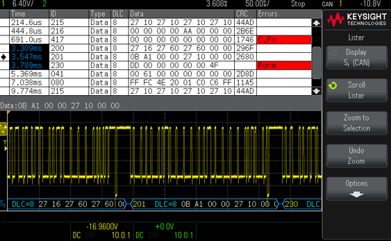
    Waveform measurements


    All Models

    Cursors

    Single cursor accuracy: ± [DC vertical gain accuracy + DC vertical offset accuracy + 0.25% full scale]


    Dual cursor accuracy: ± [DC vertical gain accuracy + 0.5% full scale]


    Units: Seconds(s), Hz (1/s), phase (degrees)

    Automatic measurements

    Select up to 4 continuously updated measurements from a list of 32 available amplitude, timing, and count measurements

    Cursors track last selected measurement

    Use default (relative/%) or customizable measurement threshold levels (absolute or relative)
    Measurements automatically gated by zoom window

    Vertical/amplitude measurements (14):

    Peak-to-peak, maximum, minimum, amplitude, top, base, overshoot, preshoot, average-N cycles, average-full screen,
    DC RMS-N cycles, DC RMS-full screen, AC RMS-N cycles, AC RMS-full screen (standard deviation)

    Timing measurements (14):

    Period, frequency, counter, +width, -width, +duty cycle, -duty cycle, bit rate, rise time, fall time,
    delay, phase, X at min Y, X at max Y

    Count measurements (4):

    +pulse count, -pulse count, rising edge count, falling edge count
    Snapshot:

    Performs 24 parametric measurements once (not updated) on a single source (ch1, ch2, ch3, or ch4) one time

    Automatic measurement logging: Available via BenchVue BV0004B (standard)


    Find us at www.keysight.com Page 16

    Performance Characteristics (continued)


    Waveform math


    All Models

    Math functions

    Add, subtract, multiply, divide, FFT (magnitude), FFT (phase), low-pass filter

    Record size

    Up to 64 k points resolution

    FFT

    Window types: Hanning, Flat top, Rectangular, Blackman-Harris
    Vertical scaling: dB (logarithmic) or RMS (linear)

    Horizontal scaling: User-defined span and center frequency settings, or Auto Setup


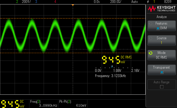
    Digital voltmeter (standard)


    All Models

    Functions

    DC, AC-rms, DC-rms

    Resolution

    3 digits

    Measuring rate

    100 times/second

    Auto ranging

    Automatic adjustment of vertical amplification to maximize the dynamic range of measurements

    Range meter

    Graphical display of most recent measurement, plus extrema over the previous 3 seconds


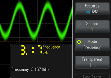
    Frequency counter (standard)


    All Models

    Functions

    Frequency

    Resolution

    5 digits

    Measuring rate

    100 times/second

    Auto ranging

    Automatic adjustment of vertical amplification to maximize the dynamic range of measurements

    Range meter

    Graphical display of most recent measurement, plus extrema over the previous 3 seconds


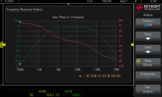
    Frequency response analysis - Bode plot (standard on “G” models)


    EDUX1052G/ DSOX1202G/ DSOX1204G

    Dynamic range

    > 80 dB (typical, based on 0 dBm (630 mVpp) input into 50-Ω load

    Input test source

    WaveGen out

    VIN and VOUT

    Channel 1, 2, 3, and 4 (channel 3 and 4 on 4-channel models only)

    Frequency range

    10 Hz to 20 MHz

    Number of test points

    1 to 1000 points across selected frequency range

    Test amplitude

    1 mVpp to 9 Vpp into 50-Ω

    Test results

    Overlaid logarithmic gain (dB) and linear phase (degrees) plots versus logarithmic frequency

    Manual measurements

    A single pair of tracking gain and phase markers at user-defined frequency setting

    Plot scaling

    Auto-scaled during test with user-defined scaling after test


    Find us at www.keysight.com Page 17

    Performance Characteristics (continued)


    WaveGen – Built-in function generator (standard on “G” models)

    Note: Only available on WaveGen models EDUX1052G, DSOX1202G, and DSOX1204G. WaveGen is not upgradeable.


    EDUX1052G/ DSOX1202G/ DSOX1204G

    WaveGen out

    Front-panel BNC connector

    Waveforms

    Sine, square, ramp, pulse, DC, noise

    Modulation

    Modulation types: AM, FM, FSK


    Carrier waveforms: Sine, ramp


    Modulation source: Internal (no external modulation capability)


    AM:


    – Modulation: sine, square, ramp


    – Modulation frequency: 1 Hz to 20 kHz


    – Depth: 0 to 100%


    FM:


    – Modulation: sine, square, ramp


    – Modulation frequency: 1 Hz to 20 kHz


    – Minimum carrier frequency: 10 Hz


    – Deviation: 1 Hz to carrier frequency or (2e12 / carrier frequency), whichever is smaller


    FSK:


    – Modulation: 50% duty cycle square wave


    – FSK rate: 1 Hz to 20 kHz


    – Hop frequency: 2 x FSK rate to 10 MHz

    Sine

    Frequency range: 0.1 Hz to 20 MHz


    Amplitude flatness: ± 0.5 dB (relative to 1 kHz)


    Harmonic distortion: —40 dBc


    Spurious (non-harmonics): —40 dBc


    Total harmonic distortion: 1%


    SNR (50 Ω load, 500 MHz bandwidth): 40 dB (typical); 30 dB (min)

    Square wave /pulse

    Frequency range: 0.1 Hz to 10 MHz


    Duty cycle: 20 to 80%


    Duty cycle resolution: Larger of 1% or 10 ns


    Pulse width: 20 ns minimum


    Rise/fall time: 18 ns (10 to 90%)


    Pulse width resolution: 10 ns or 5 digits, whichever is larger


    Overshoot: < 2%


    Asymmetry (at 50% DC): ± 1% ± 5 ns


    Jitter (TIE RMS): 500 ps

    Ramp /triangle wave

    Frequency range: 0.1 Hz to 200 kHz


    Linearity: 1%


    Variable symmetry: 0 to 100%


    Symmetry resolution: 1%

    Noise

    Bandwidth: 20 MHz typical


    Find us at www.keysight.com Page 18

    Performance Characteristics (continued)


    WaveGen – Built-in function generator (continued)

    Note: Only available on WaveGen models EDUX1052G, DSOX1202G, and DSOX1204G. WaveGen is not upgradeable.


    EDUX1052G/ DSOX1202G/ DSOX1204G

    Frequency

    Sine wave and ramp accuracy:


    130 ppm (frequency < 10 kHz)


    50 ppm (frequency > 10 kHz)


    Square wave and pulse accuracy:


    [50 + frequency/200] ppm (frequency < 25 kHz)


    50 ppm (frequency ≥ 25 kHz)


    Resolution: 0.1 Hz or 4 digits, whichever is larger

    Amplitude

    Square, Pulse, Ramp:


    2 mVpp to 20 Vpp into Hi-Z (offset ≤ ±0.4 V)


    1 mVpp to 10 Vpp into 50 Ω (offset ≤ ±0.4 V)


    50 mVpp to 20 Vpp into Hi-Z (offset > ±0.4 V)


    25 mVpp to 10 Vpp into 50 Ω (offset > ±0.4 V)


    Sine:


    2 mVpp to 12 Vpp into Hi-Z (offset ≤ ± 0.4 V)


    1 mVpp to 9 Vpp into 50 Ω (offset ≤ ± 0.4 V)


    50 mVpp to 12 Vpp into Hi-Z (offset > ± 0.4 V)


    25 mVpp to 9 Vpp into 50 Ω (offset > ± 0.4 V)


    Resolution: ≤ 1% of the amplitude


    Accuracy: 2% (Frequency = 1 kHz)

    DC offset

    Square, Pulse, Ramp:


    ± [10 V – ½ amplitude] into Hi-Z


    ± [5 V – ½ amplitude] into 50 Ω


    Sine:


    ± [8 V – ½ amplitude] into Hi-Z


    ± [4.5 V – ½ amplitude] into 50 Ω


    Resolution: Larger of 100 µV or 3 digits


    Accuracy: ± 1.5% of offset setting ± 1.5% of amplitude ± 1 mV

    Main output

    Impedance: 50 Ω typical


    Isolation: Not available, main output BNC is grounded


    Protection: Overload automatically disables output


    Sine, square, ramp, pulse, DC, noise


    Find us at www.keysight.com Page 19

    Performance Characteristics (continued)


    Connectivity


    All Models

    Standard Ports

    One USB 2.0 hi-speed device port on rear panel. Supports USBTMC protocol


    One USB 2.0 hi-speed host port on front panel. Supports memory devices


    One Ethernet 1 Gb/s networking: RJ-45


    Nonvolatile storage


    All Models

    Reference waveform display

    Two internal waveforms or USB thumb drive

    Waveform/data storage

    Setups (.scp), images (.bmp, .png), channel waveforms (.csv, .bin), reference waveforms (.h5), mask (.msk),
    serial protocol data (.csv), Bode gain & phase data (.csv)

    Max USB flash drive size

    Supports industry standard flash drives

    Setups without USB flash drive

    10 internal setups

    USB drive format

    FAT32 , NTFS, EXT2/3/4


    General and environmental characteristics


    All Models

    Power line consumption

    50 W max

    Power voltage range

    100 to 120 V, 50/60/400 Hz; 100 to 240 V, 50/60 Hz

    Environmental rating

    0 to +50 °C, 3,000 m Max


    Maximum Relative Humidity (non-condensing): 95%RH up to 40°C, decreases linearly to 45%RH at 50°C 11

    Electromagnetic compatibility

    Meets EMC directive (2004/108/EC), meets or exceeds IEC 61326-1:2005/EN61326-1:2013 (basic)


    IEC 61000-4-2/EN 61000-4-2


    IEC 61000-4-3/EN 61000-4-3


    IEC 61000-4-4/EN 61000-4-4


    IEC 61000-4-5/EN 61000-4-5


    IEC 61000-4-6/EN 61000-4-6


    IEC 61000-4-8/EN 61000-4-8


    IEC 61000-4-11/EN 61000-4-11


    Canada: ICES/NMB-001:2006


    Australia/New Zealand: AS/NZS CISPER 11:2011

    Safety

    ANSI/UL Std. No. 61010-1:2012; CAN/CSA-C22.2 No. 61010-1-12


    ANSI/UL Std. No. 61010-2-030:2012; CAN/CSA-C22.2 No. 61010-2-030-12

    Dimensions (W x H x D)

    314 mm (12.4 in) x 165 mm (6.5 in) x 130 mm (5.1 in)

    Weight

    Net: 3.23 kg (7.1 lbs.), shipping: 4.2 kg (9.2 lbs.)

    Display

    7.0” diagonal color TFT LCD WVGA

  11. From 40 °C to 50 °C, the maximum % relative humidity follows the line of constant dew point.


Configuring your InfiniiVision 1000 X-Series Oscilloscope


Step 1: Choose your oscilloscope


EDUX1052A

50 MHz, 2 channels

EDUX1052G

50 MHz, 2 channels with function generator

DSOX1202A

70/100/200 MHz, 2 channels

DSOX1202G

70/100/200 MHz, 2 channels with function generator

DSOX1204A

70/100/200 MHz, 4 channels

DSOX1204G

70/100/200 MHz, 4 channels with function generator


Step 2: Select bandwidth options

Model: DSOX1202A/G (2-channel models)


DSOX1202-070

70 MHz bandwidth option

Compatible with DSOX1202A or DSOX1202G

DSOX1202-100

100 MHz bandwidth option

Compatible with DSOX1202A or DSOX1202G

DSOX1202-200

200 MHz bandwidth option

Compatible with DSOX1202A or DSOX1202G


Model: DSOX1204A/G (4-channel models)


DSOX1200-070

70 MHz bandwidth option

Compatible with DSOX1204A or DSOX1204G

DSOX1200-100

100 MHz bandwidth option

Compatible with DSOX1204A or DSOX1204G

DSOX1200-200

200 MHz bandwidth option

Compatible with DSOX1204A or DSOX1204G


Step 3: Select optional accessories


DSOXBODE

Bode plot training kit

Option

N2137A

User's Guide (hardcopy) for InfiniiVision 1000 X-Series

Option (electronic copy downloadable at no charge)

N2738A

Soft carrying case for 1000 X-Series oscilloscopes

Option

N2138A

Rackmount kit for 1000 X-Series oscilloscopes

Option


Step 4: Select optional PC-based test automation and documentation software


BV0004B

BenchVue oscilloscope application

Standard

D9010UDAA

User-defined Application (UDA) software

Option

D9010BSEO

Infiniium Offline Oscilloscope Analysis Software

Option


Find us at www.keysight.com Page 21

Configuring your InfiniiVision 1000X-Series Oscilloscope (continued)


Step 5: Select optional probes

Passive Probes


N2142A

1:1, 10:1 switchable 75 MHz passive probe

2 probes included standard with EDUX1052A/G

N2140A

1:1, 10:1 switchable 200 MHz passive probe

2 probes included standard with DSOX1202A/G
4 probes included standard with DSOX1204A/G

N2842A

10:1, 300 MHz passive probe

Option

N2889A

1:1, 10:1 switchable 350 MHz passive probe

Option

10070D

1:1, 20 MHz passive probe

Option

N2870A

1:1, 35 MHz passive probe

Option

N7007A

10:1 400 MHz extreme temperature passive probe

Option

10076C

100:1 500 MHz 3.7 KV high voltage passive probe

Option


Differential Probes


N2791A

25 MHz, 10:1, 100:1 switchable high voltage up to ± 700V

Option

N2891A

70 MHz, 100:1, 1000:1 switchable high voltage up to ± 7000V

Option


Current Probes


1146B

100 kHz, 100A, AC/DC current probe

Option

N2780B

2 MHz, 500A, AC/DC current probe (with N2779A power supply)

Option

N2781B

10 MHz, 150A, AC/DC current probe (with N2779A power supply)

Option

N2783B

50 MHz, 30A, AC/DC current probe (with N2779A power supply)

Option

N2783B

100 MHz, 30A, AC/DC current probe (with N2779A power supply)

Option

N7040A

23 MHz, 3 kA, AC current probe (Rogowski coil)

Option

N7041A

30 MHz, 600A, AC current probe (Rogowski coil)

Option

N7042A

30 MHz, 300A, AC current probe (Rogowski coil)

Option


Step 6: Select language options (hard copy of user’s guide is not included unless ordered)


Front panel overlay
(EDUX1052A/G, DSOX1202A/G)

Front panel overlay
(DSOX1204A/G)

User's guide
(All models)

English

Standard

Standard

N2137A-ABA

Chinese (Simplified)

DSOX1202-AB2

DSOX1200-AB2

N2137A-AB2

Chinese (Traditional)

DSOX1202-AB0

DSOX1200-AB0

N2137A-AB0

Czech

DSOX1202-AKB

DSOX1200-AKB

Not available

French

DSOX1202-ABF

DSOX1200-ABF

N2137A-ABF

German

DSOX1202-ABD

DSOX1200-ABD

N2137A-ABD

Italian

DSOX1202-ABZ

DSOX1200-ABZ

N2137A-ABZ

Japanese

DSOX1202-ABJ

DSOX1200-ABJ

N2137A-ABJ

Korean

DSOX1202-AB1

DSOX1200-AB1

N2137A-AB1

Polish

DSOX1202-AKD

DSOX1200-AKD

Not available

Portuguese

DSOX1202-AB9

DSOX1200-AB9

N2137A-AB9

Russian

DSOX1202-AKT

DSOX1200-AKT

N2137A-AKT

Spanish

DSOX1202-ABE

DSOX1200-ABE

N2137A-ABE

Thai

DSOX1202-AB3

DSOX1200-AB3

Not available

Turkish

DSOX1202-AB8

DSOX1200-AB8

Not available


Find us at www.keysight.com Page 22

Configuring your InfiniiVision 1000X-Series Oscilloscope (continued)


Included standard


Standard passive probes (Two N2142A for EDUX1052A/G;

Two N2140A for DSOX1202A/G;

Four N2140A for DSOX1204A/G)

Standard secure erase

Interface language support GUI: English, Japanese, Simplified Chinese, Traditional Chinese, Korean, German, French, Spanish, Russian, Portuguese, Italian,
Polish, Czech, Thai, and Turkish

Built-in help language support for English, Japanese, Simplified Chinese, Traditional Chinese, Korean, German, French, Spanish, Russian, Portuguese, Italian,
Polish, and Thai

Localized Power cord

Standard 3-year warranty (90 days for non-serialized accessories)

Soft copy of Certificate of Calibration (CoC) downloadable from https://service.keysight.com/infoline/public/details.aspx?i=DOCl


After-purchase bandwidth upgrades

Model: DSOX1202A/G (2-channel models)


D1202BW1A

Upgrade bandwidth from 70 to 100 MHz

Compatible with DSOX1202A or DSOX1202G

D1202BW2A

Upgrade bandwidth from 70 to 200 MHz

Compatible with DSOX1202A or DSOX1202G

D1202BW3A

Upgrade bandwidth from 100 to 200 MHz

Compatible with DSOX1202A or DSOX1202G